As solar plant owners channel efforts towards strengthening the performance and efficiency of their operations, DC cabling selection cannot be overlooked. Based on the interpretation of IEC standards, and considering factors such as safety, bifacial gains, cable carrying capacity, cable loss, and voltage drop, plant owners can determine the appropriate cabling to ensure safe, stable operation across a PV system’s life cycle.
Solar module performance in the field is greatly affected by environmental conditions. The short circuit current on a PV module datasheet is based on standard testing conditions, including irradiance of 1 kW/m2, a spectrum air mass of 1.5, and a cell temperature of 25 C. The datasheet current does not consider the rear surface current in bifacial modules either, so factors such as cloud enhancement; temperature; irradiance spikes; and albedo-driven over-irradiance on the rear surface can significantly affect the actual short circuit current for PV modules.
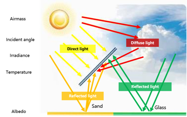
Image: Huawei
Pick the right cables
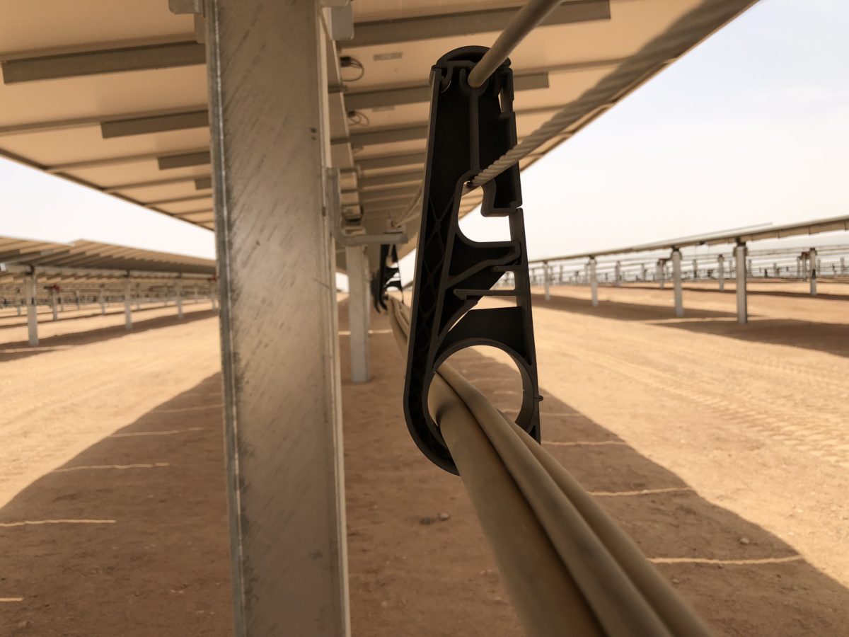
DC cables are PV system lifelines as they interconnect modules to combiner boxes and inverters.
Plant owners must ensure the size of cable is carefully chosen for the current and voltage of the PV system. Cables used for wiring the DC section of a grid-connected PV system also need to withstand potential extremes of environmental, voltage, and current conditions. This includes the heating effects of both current and solar gain, especially if installed near the modules.
Here are some crucial considerations.

Image: Huawei
Settling cabling design
In PV system design, short-term cost considerations can result in poor equipment selection and lead to safety and performance issues in the long run, including catastrophic consequences such as fires. The following areas need to be carefully assessed to meet national safety and quality standards:
- Voltage drop limit: Losses in solar PV cabling must be limited, both DC losses in the strings of solar panels and AC losses at the output of inverters. A way to limit these losses is to minimize the voltage drop in cables. In general, a DC voltage drop of less than 1% is desirable and the figure must not exceed 2%. A high DC voltage drop also increases voltage dispersion of the PV strings connected to the same maximum power point tracking (MPPT) system, resulting in higher mismatch losses.
- Cable loss: To ensure energy yield, it is recommended cable loss of the entire LV cable (from modules to transformer) should not exceed 2%, ideally 1.5%.
- Current carrying capacity: Derating factors should be taken into consideration, such as the method of laying cables, temperature rises, laying distance, and number of parallel cables, which reduce the current carrying capacity of cables.
IEC standards for bifacial
Standards are essential for ensuring the reliability, safety, and quality of PV systems, including cabling. Globally, there are several recognized standards for the use of DC cables. One of the most comprehensive sets are the IEC standards.
IEC 62548 sets out design requirements for PV arrays, including DC array wiring, electrical protection devices, switching, and earthing provisions. The latest draft of IEC 62548 specifies the current calculation method for bifacial modules. IEC 61215:2021 outlines the definition and test requirements of bifacial PV modules. It introduces the solar irradiance test conditions of bifacial modules. Namely, BNPI (bifacial nameplate irradiance): the front side of the PV module receives 1 kW/m2 solar irradiance and the rear 135 W/m2; and BSI (bifacial stress irradiance), where the photovoltaic module receives 1 kW/m2 solar irradiance on the front and 300 W/m2 on the rear.
Overcurrent protection
An overcurrent protection device is used to guard against the potentially dangerous effects of overloads, short-circuits, or ground faults. The most common overcurrent protection devices are circuit breakers and fuses.
The overcurrent protection device will cut off the circuit when the reverse current exceeds the current protection value, so the forward and reverse currents flowing through the DC cable will never be higher than the rated current of the device. In this case, the DC cable should have a carrying capacity equal to the rated current of the overcurrent protection device.
The formula
Overcurrent protection nominal rating In=1,1 ´ NSA´ ISTRING MAX. Where NSA is the number of strings in parallel, ISTRING MAX is the max current of the PV strings: ISTRING MAX = 1,25 * KCorr x ISC MOD,Where Kcorr is a location and design correction factor. For bifacial modules it is usually 1.1 (however it can be determined by other methods described in IEC62548). ISC MOD is the module short circuit current.
If there is no overcurrent protection device in the circuit, plant owners need to consider the maximum forward current and maximum reverse current that may flow through the DC cable and then take the larger value of the two when selecting the cable.
Installation conditions
When designing and installing DC cabling, it's essential to calculate the current-carrying capacity of the cable under certain field conditions, to ensure the cable is not overloaded. An empirical formula can be used to determine the current carrying capacity of the cable after derating (Iz): The formula includes various factors affecting the nominal current carrying capacity (I0) including different soil temperatures (f1), multiple cables laid in parallel directly in the soil (f2), soil thermal resistance (f3), and buried depths (f4).
A Middle East case study
The PV array comprises: Bifacial modules, generating 540 W with maximum power usage; a rated voltage of 41.3 V, a maximum power point current of 13.13 A, a short-circuit current of 13.89 A, and 70% bifaciality of the PV modules; 28 modules in series in a PV string; the photovoltaic support adopts a horizontal single-axis tracking system and the height above ground is 1.5 m; a DC combiner box with 16-in and 1-out is adopted; The whole PV array has 30 DC combiner boxes integrated into centralized inverters; Kcorr is 1.1, which is simulated by PVsyst software; desired cable current carrying capacity Iz=In=1,1 ´ NSA´ ISTRING MAX=1.1*16*1.25*1.1*13.89=336.14A; Total derating factor: Ktot= 0.93´0.75´0.8´1=0.558; and cable nominal current-carrying capacity: I0=Iz/Ktot=336.14/0.558=602.4A.
Based on the PV array configuration, the nominal current carrying capacity of the DC cable used in this case should be greater than 602.4 A.
The nominal current carrying capacity of the cable is selected based on the manufacturer's datasheet (or according to cable selection standard IEC60364-5-52, but the corresponding derating coefficient must also be selected according to that standard).
The formula resulted in a recommendation of two parallel, 2×300 mm2 aluminum DC cables from the PV string combiner box to the inverter. The cable length was also reviewed to ensure that the voltage drop of the DC cable, and total cable losses, met project-specified requirements. To ensure the DC voltage drop is less than 2%, the specifications of some long-distance cables should be increased from 2×300 mm2 to 2×400 mm2. It should also be noted the cable laying coefficient will be further reduced when two cables are laid in parallel.
Due to the radiation, temperature rise, gain at the back of the bifacial modules, and the derating coefficient of the cables, DC cables with a thicker diameter will be applied, increasing cost. With the purpose of controlling costs and ensuring plant safety, the DC cable length should be shortened or the DC current should be limited by power electronics equipment such as string inverters.
Equipment selection and inverters
In a central inverter configuration, multiple PV strings are connected in parallel into a DC combiner box, and multiple combiner boxes are connected, in parallel, into the inverter.
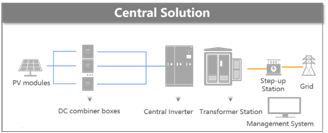
Image: Huawei
Therefore, the maximum output current at the combiner box and the input current at the inverter are constantly varying and of significant uncertainty. There are safety risks and additional design margins that must be considered during electrical equipment selection (of fuses, disconnectors, and cables in the PV sub-array and PV array), which significantly increase the final balance-of-system cost.
By contrast, string inverter solutions convert fluctuating, uncertain energy on the PV side into controllable electricity output. The inverter limits the current output. Thus, the diameter of the inverter output cable does not need to consider changes in light and temperature or bifaciality. This enables designers to select the most cost-effective cables and overcurrent protection devices. Moreover, string inverters have a shorter DC cable and lower DC voltage drop, which results in less mismatch loss and more inherent electricity generation.
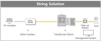
Image: Huawei
Unlike conventional power plants, the operating current of PV modules is greatly affected by environmental conditions and bifacial gain. These factors need to be fully considered in cable selection during the design phase, along with restrictions on voltage drop and cable losses, to ensure the long term return on investment of PV plants.
The views and opinions expressed in this article are the author’s own, and do not necessarily reflect those held by pv magazine.
This content is protected by copyright and may not be reused. If you want to cooperate with us and would like to reuse some of our content, please contact: editors@pv-magazine.com.

2 comments
By submitting this form you agree to pv magazine using your data for the purposes of publishing your comment.
Your personal data will only be disclosed or otherwise transmitted to third parties for the purposes of spam filtering or if this is necessary for technical maintenance of the website. Any other transfer to third parties will not take place unless this is justified on the basis of applicable data protection regulations or if pv magazine is legally obliged to do so.
You may revoke this consent at any time with effect for the future, in which case your personal data will be deleted immediately. Otherwise, your data will be deleted if pv magazine has processed your request or the purpose of data storage is fulfilled.
Further information on data privacy can be found in our Data Protection Policy.