Scientists at the University of Padova in Italy have built a residential heat pump prototype that utilizes an air-finned coil heat exchanger or photovoltaic-thermal (PVT) solar collectors as the evaporator.
In the study “Experimental and numerical analysis of a CO2 dual-source heat pump with PVT evaporators for residential heating applications,” published in Applied Thermal Engineering, the Italian group described the system as a 5 kW direct-expansion solar-assisted heat pump (DX-SAHP) operating with CO2 as the refrigerant and a transcritical cycle to produce hot water at the gas cooler (GC).
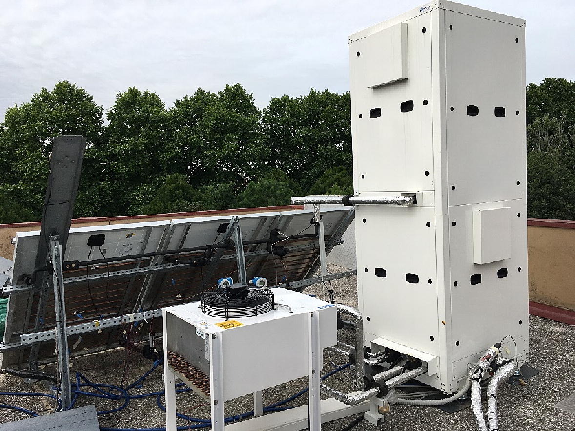
It consists of a compressor, a gas cooler, a throttling valve, an internal heat exchanger, two water tanks, and the above-mentioned two evaporator technologies, which the team said can work alternatively.
The finned coil has 22 ranks and 4 rows and is coupled to a fan driven by a 0-10 Vdc signal to modulate the rotation speed. The PVT system used includes an aluminum plate with a thickness of 0.5 mm glued below a polycrystalline PV module. The aluminum plate is connected to an 8 mm external diameter copper serpentine. The gas cooler is a brazed plate heat exchanger made of 28 plates with external dimensions of 379 x 79 mm.
“After the gas cooler, the refrigerant enters an internal heat exchanger (INT), where the CO2 is cooled down,” the researchers explained referring to how the heat pump works. “Subsequently, it is expanded into an electronic expansion device (EEV) that operates as a back-pressure valve to control the pressure at the gas cooler.” The CO2 is conveyed then to the low-pressure receiver tank (REC), where the vapor phase is extracted from the top and pushed to the compressor through the internal heat exchanger.
The heat pump extracts cold water from a dedicated tank called Tank1 and sends it via a water pump to the gas cooler, which heats the water before it is stored in a hot tank dubbed Tank2. “In Tank1, four variable electrical resistances, capable of producing up to 4.5 kW each, allow controlling the tank’s temperature and, consequently, the water temperature at the inlet of the gas cooler,” the academics explained. “The refrigerant circuit and the water loop are thermally insulated to limit the heat losses towards the external ambient.”
Through the TRNSYS software, which is used to simulate the behavior of transient renewable systems, the researchers conducted a series of experimental tests alternating both evaporator technologies. They found that, when operating with the PVT system, the PV panel achieves an 8% increase in photovoltaic power production due to the cooling effect of the refrigerant evaporating in the collectors.
They also found, however, that, when working in the solar mode, the simulated coefficient of performance (COP) of the heat pump is 2.58, 2% lower than the value estimated through the experimental tests. “In conclusion, the validated model is a useful tool for performing seasonal simulations of a CO2 heat pump operating in solar and air modes,” they stated. “Future works will focus on developing a control strategy to select the thermal sources to maximize the benefits of a similar dual-source system.”
This content is protected by copyright and may not be reused. If you want to cooperate with us and would like to reuse some of our content, please contact: editors@pv-magazine.com.


1 comment
By submitting this form you agree to pv magazine using your data for the purposes of publishing your comment.
Your personal data will only be disclosed or otherwise transmitted to third parties for the purposes of spam filtering or if this is necessary for technical maintenance of the website. Any other transfer to third parties will not take place unless this is justified on the basis of applicable data protection regulations or if pv magazine is legally obliged to do so.
You may revoke this consent at any time with effect for the future, in which case your personal data will be deleted immediately. Otherwise, your data will be deleted if pv magazine has processed your request or the purpose of data storage is fulfilled.
Further information on data privacy can be found in our Data Protection Policy.