

To view a recording of this webinar, please click here
Do you see a performance difference between glass-glass and transparent backsheet bifacial modules?
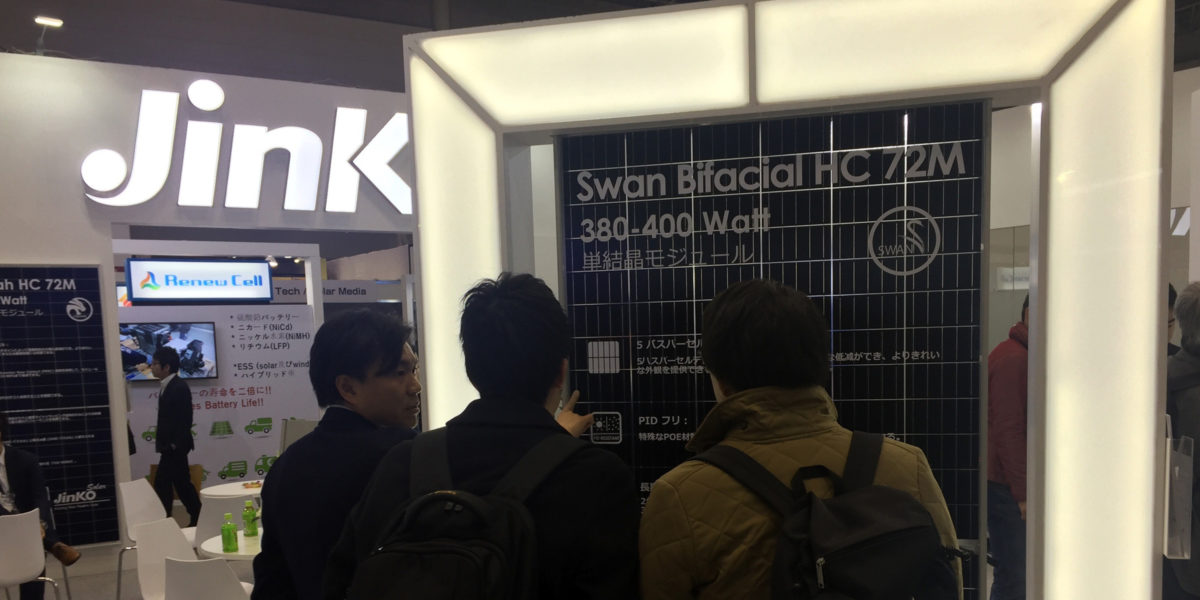
Andrea Viaro: Bifacial modules from JinkoSolar are produced using only Tedlar-based transparent backsheet from DuPont, which is the most reliable and stable material available in the industry for PV application. Tedlar is stable against UV light and humidity in particular, which allows us to achieve performance levels in the long-term comparable to glass-glass bifacial modules.
Teun Burgers: We have no experience in differences in optical or electrical properties between those module types. We have some indication that glass-glass modules operate at lower temperatures because of differences in heat transfer coefficient between glass and backsheet. M. W. P. E. Lamers, et al., Solar Energy Materials and Solar Cells 185, 192 (2018).
What are the maximum (worst-case) output current guarantees for bifacial modules, needed for project sign-off purposes.
AV: The bifacial module guarantees are very much related to the BSTC standard guidelines and nameplate rating, the latter in particular is still under discussion. JinkoSolar is considering a Total Power Warranty for bifacial modules with similar conditions as for mono-facial modules, according to the official BSTC criteria and the official power rating for bifacial modules that will be finally implemented.
DC to AC Ratio: When you are showing a ratio of 1.2 is the bifacial gain assumed in the DC rating of the system (gain as modeled) or is that only assuming front side rating?
AV: The DC/AC ratio for bifacial systems can be estimated dividing the DC/AC ratio for the equivalent monofacial system (i.e. only front side) by the bifacial gain + 1 with the following empirical formula:
Bifacial DC/AC ratio = monofacial DC/AC ratio / ( 1 + bifacial power gain)
TB: In our case we use for the DC power the front side (nameplate) power only.
What is the best way to estimate the albedo factor for a project if there is no time for yearly measurement?
Even when directly measuring the albedo for the specific site where the system will be deployed, we still need to consider variation caused by the PV array itself. There are already different databases available and implemented in the most common simulation software that can be used for energy yield estimations with acceptable tolerance level.
In your experience, does PVsyst afford adequate levels of accuracy for yield estimation or more advanced approached (e.g. those on based on ray tracing) should be resorted to?
The model used in PVSyst is the “unlimited sheds” model: an array of infinitely long rows, at constant pitch. Finite length effects of the sheds need to be accounted for in the user-specified “mismatch loss factor”. If your system is sufficiently similar to the PVsyst assumption this is adequate.
Programs such as BIGEYE are suited for situations where this is not the case. Since the irradiance is calculated fully 3D in bigeye, inhomogeneities in irradiance are propagated into the current of the cells and accounted for.
How could we simulate bifacial gain for complex terrains?
Complex terrain is a rather broad term. It could entail slopes, or additional shading elements to some degree. This has to be done on a case by case basis. The important values are the expected annual kWh-yield and the cost of the total installation for monofacial and bifacial system designs. Based on those, you make your business decision. The bifacial gain is a simplified number to indicate how much more kWh you expected under your assumptions what to keep fixed and what to vary.
Is it better to use optimizers or string inverters with bifacial modules?
AV: Complexity increases necessarily with bifacial systems, and mismatch loss risk increases proportionally if the PV array design and BOS configuration is not optimized. When using string inverters instead of central, and stringing modules appropriately, the MPPTs granularity increases significantly and mismatch losses are also reduced accordingly.
What should be the mismatch loss assumption for bifacial systems?
TB: In the bigeye software we calculate this implicitly, but have not reported or calculated what the mismatch loss is compared to an infinitely long homogeneous system.
What should be the rear side soiling loss percentage?
I do not think there is (much) field data on this. It will depend on location, climate and probably on rear panel properties. Mind that a 3% loss due to rear soiling is 3% of say 10% gain, thus a minus of 0.3% on the annual energy yield.
We are aware of an experiment being carried out currently on a highway noise barrier where different sections receive different cleaning schedules. But these panels are nearly vertical.
How can Jinko’s Swan module reduce the cost of the BOS?
AV: Bifacial technology enables to increase the total module power, and the energy yield rises accordingly. A proportional BOS costs reduction is there for achievable, for mounting structure components for instance, for the same installation nominal peak power
Why does the mounting structure with trackers have to be higher (1.5m) compared to 1.2m for fixed systems? Is it due to additional shading caused by trackers?
TB: For direct light the irradiance on the ground does not change with ground clearance. For both bifacial trackers and fixed tilt systems, higher racks can provide better access for diffuse light to the ground and increase the reflected contribution from the ground. Also, with higher ground clearance, the irradiance on the rear side becomes more homogeneous, as points on the rear side get more of the ground in view.
For trackers you want a certain clearance between bottom edge and ground. As trackers have higher tilt angles (some of the time) this means higher “axis” z-value. Trackers are positioned more perpendicular to the sun, harvesting more energy, but that does come at the expense of more shading of direct light on the ground.
Are there any design guidelines available for applications like carports, commercial white membrane roofs, and residential white shingle and metal roofs?
AV: Bifacial technology can be applied to many different PV system types and enables to optimize the power gain in case of rooftop installations for instance, where the light reflection can be increased by means of white painting/surfaces, or in carports, where bifacial modules can benefit from the higher rear-side irradiance thanks to the elevated position from ground of the mounting structure.
Is it possible to have information regarding the GCR of the sites tested?
AV: The case studies presented during the webinar describe the results from Jinko R&D test center where single PV module arrays are studied. For more information about GCR optimization about Bifacial systems we recommend to refer to the White Paper recently released by JinkoSolar.
To view a recording of the webinar, or to download slides from the two presentations, please click here.
This content is protected by copyright and may not be reused. If you want to cooperate with us and would like to reuse some of our content, please contact: editors@pv-magazine.com.


By submitting this form you agree to pv magazine using your data for the purposes of publishing your comment.
Your personal data will only be disclosed or otherwise transmitted to third parties for the purposes of spam filtering or if this is necessary for technical maintenance of the website. Any other transfer to third parties will not take place unless this is justified on the basis of applicable data protection regulations or if pv magazine is legally obliged to do so.
You may revoke this consent at any time with effect for the future, in which case your personal data will be deleted immediately. Otherwise, your data will be deleted if pv magazine has processed your request or the purpose of data storage is fulfilled.
Further information on data privacy can be found in our Data Protection Policy.